Line Sizing Calculator
Calculate pressure drop and head loss for pipe systems with up to 3 pipe sections. Uses Darcy-Weisbach equation with Moody friction factor.
Incompressible Line Sizing Calculator Guide (PDF)
This calculator determines the pressure drop through a pipeline. It is suitable for incompressible flow. Incompressible flow refers to liquids in all cases and gases or vapours where the pressure drop is less than 10% of the upstream pressure. This calculator can also be used for gases or vapours where the pressure drop is up to 40% of the upstream pressure if the average fluid density is used.
The calculator determines the static pressure drop and frictional pressure drop through a line assuming incompressible flow.
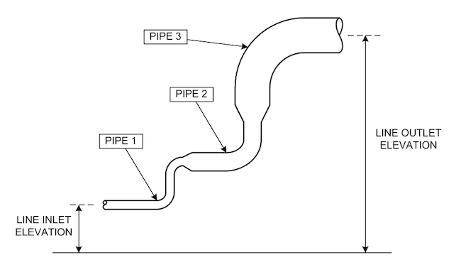
Up to 3 pipes of different diameters can be handled in the calculation of the line pressure drop.
- Enter the source and destination of the line and the line number
- Enter the fluid details and physical properties
- Enter the elevations of each end of the line
- Choose the nominal diameter and schedule of 1, 2 or all 3 pipes from the drop down lists
- The calculator will determine the inside diameter of each selected pipe
- Enter a length for 1, 2 or all 3 pipes
- Enter an absolute roughness for each pipe. Typical values:
- Commercial steel: 0.046 mm
- Drawn tubing (brass, lead, glass): 0.002 mm
- Asphalted cast iron: 0.122 mm
- Galvanized iron: 0.152 mm
- Cast iron: 0.259 mm
- Enter the quantities of each type of fitting for each pipe if known
- If the type and quantities of each fitting are unknown, enter a fitting factor. Typical factors for 50 metre long lines:
- 3" diameter and smaller: 1.5
- 4" and 6" diameter: 2.0
- 8" diameter and larger: 2.5
- Click the "Calculate" button
- The calculator will determine the static and frictional pressure drop through 1, 2 or all 3 pipes making up the line
- "Reasonable" fluid velocities:
- Liquids: up to 3 m/s
- Gases: up to 20 m/s
Download Calculation Report
Get this calculation as a professional PDF with full methodology, equations and substituted values — ready for your project file.